

Power Train Unit (PTU)
Build critical power capacity through standardized, repeatable power blocks that move complex integration work from the project site into a controlled factory environment.
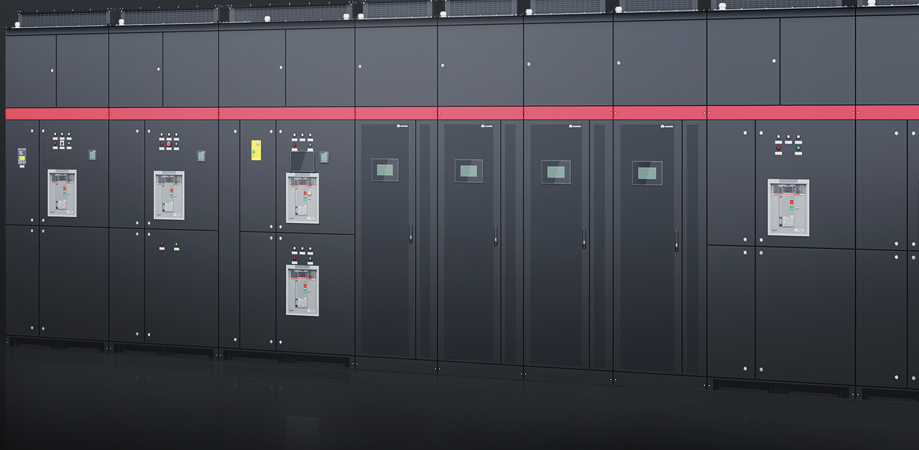
What Is a Power Train Unit?
A Power Train Unit transforms critical electrical infrastructure from a collection of separately constructed systems into a standardized, repeatable functional module.
Instead of installing and interconnecting every UPS, battery system, switchboard, control system and supporting component independently at site, a PTU moves a significant portion of system integration, testing and pre-commissioning into the factory.
The result is a more controlled delivery model that can help simplify site construction, standardize capacity blocks and support phased data center expansion.
A Power Train Unit (PTU) is a standardized and repeatable power-infrastructure building block that integrates a defined portion of the electrical power path and its supporting systems into a controlled functional module.
The container is only one possible physical form. The real design starts with the functional power boundary, capacity, redundancy and interfaces required by the data center.
Simplify How Critical Power Is Designed and Delivered
PTU architecture converts major parts of the power infrastructure into repeatable engineered blocks, reducing reliance on large-scale site assembly.
Factory Integration
Move assembly, internal interconnection, inspection and pre-commissioning into a controlled production environment.
Faster Deployment
Allow module production and site preparation to run in parallel while reducing complex field installation activities.
Repeatable Capacity
Scale infrastructure by deploying standardized power blocks instead of repeatedly redesigning one increasingly large central power room.
Controlled Interfaces
Define clear boundaries between source, transformation, UPS, energy storage, distribution, monitoring and downstream loads.
From Source to Critical Load
The exact functional boundary varies by project. A complete power train can extend from the utility or generator interface to the final distribution feeding IT and critical mechanical loads.
Transformer, MV equipment, generator, busway and other upstream or downstream equipment may be integrated, adjacent to the PTU, or provided separately depending on the approved project architecture and scope boundary.
More Than Power Conversion
A prefabricated power module combines the electrical path with the supporting systems required to operate the infrastructure as one engineered environment.
Power Supply & Distribution
Main input, switching, protection, bypass, UPS output distribution and feeder interfaces are engineered as part of the defined power path.
UPS & Power Continuity
Modular or parallel UPS architecture provides conditioned power continuity according to the required capacity and redundancy philosophy.
Energy Storage
Battery systems provide the required ride-through period and must be engineered around autonomy, end-of-life capacity, temperature and safety.
Thermal Management
Dedicated cooling maintains the internal environment within the operating limits of critical electrical and battery equipment.
Monitoring & Control
Electrical status, environmental conditions, battery health, alarms and subsystem data can be consolidated for local and remote monitoring.
Fire & Safety
Fire detection, suppression interfaces, emergency power-off, access and safety systems are coordinated with the project fire strategy and local requirements.
Huawei PowerPOD FusionPower9000
Huawei FusionPower9000 Outdoor PowerPOD is a productized implementation of the PTU concept for medium and large data centers.
The solution integrates low-voltage power distribution, modular UPS, lithium battery, dedicated cooling, monitoring and fire-protection provisions within a prefabricated outdoor module.
Its one-power-system-per-container architecture supports repeatable deployment and phased capacity expansion while reducing extensive onsite integration work.
Designed Around Reliability, Agility and Efficiency
Integrated System Reliability
Power architecture, enclosure, battery, monitoring, cooling and safety systems are engineered as part of one coordinated module.
Factory Prefabrication
High factory integration reduces field assembly and allows more testing and pre-commissioning to be completed before delivery.
Phased Capacity Expansion
Repeatable power blocks support staged deployment so electrical infrastructure can be aligned with actual data center capacity growth.
High-Efficiency Power Path
Efficient UPS operation and busbar-based distribution are designed to reduce losses across the complete power path.
Huawei FusionPower9000 Reference Configuration
Final configuration must be selected against the approved project load, redundancy, battery autonomy, environmental conditions and system architecture.
| Product Type | Outdoor integrated power supply and distribution solution |
|---|---|
| Typical Application | Medium and large data centers, high-density and phased deployment |
| Module Concept | One power system per container |
| Reference Input Capacity | Up to 2.4 MVA per module |
| System Voltage | 380 V / 400 V / 415 V AC |
| Reference Container Size | 12,192 × 3,495 × 4,150 mm |
| UPS Platform | Huawei UPS5000-H modular UPS |
| UPS Architecture | Multiple parallel UPS configurations according to IT and mechanical load requirements |
| Energy Storage | Huawei SmartLi lithium battery system; capacity and autonomy project-specific |
| Cooling | Integrated dedicated cooling with redundancy options according to project design |
| Monitoring | ECC800-Pro local management with remote monitoring and upstream integration options |
| Outdoor Protection | IP55 reference enclosure protection |
| Structural Reference | Zone 3 seismic resistance and Grade 12 wind resistance |
| Fire & Safety | Integrated detection, EPO and fire suppression provisions subject to local code and approved fire strategy |
Technical values above represent reference Huawei FusionPower9000 configurations. Actual capacity, topology, component selection, redundancy and performance depend on the project-specific design and latest OEM documentation.
Built for Different Data Center Strategies
New Data Center Development
Standardize power blocks from the beginning and align electrical infrastructure deployment with the planned data hall rollout.
Data Center Expansion
Introduce additional capacity through repeatable modules where the site architecture supports phased expansion.
AI & High-Density Infrastructure
Address rapid capacity growth, limited internal building space and tighter project deployment schedules.
Outdoor Power Infrastructure
Decouple selected electrical infrastructure from the primary data center building and preserve valuable indoor space.
From PowerPOD to a Complete Power Train
Selecting the module is only one part of the project. The PTU must be integrated with the complete upstream and downstream electrical architecture.
IT load, rack density, redundancy, battery autonomy and expansion targets.
Define source, transformer, generator, PTU, busway and rack-distribution responsibilities.
Select capacity block, UPS architecture, battery, cooling, monitoring and redundancy.
Coordinate site readiness, installation, interconnection, testing and commissioning.
Maintenance planning, troubleshooting, system assessment and technical support.
Power Infrastructure Designed Around the Complete System
Requirement-Based Design
We start with actual load, redundancy, site condition, source strategy and future expansion—not only equipment selection.
End-to-End Power Integration
NPS coordinates the interfaces between upstream source systems, PTU, busway, critical loads, controls and monitoring.
From Supply to Commissioning
Support covers technical review, delivery coordination, installation interfaces, testing, commissioning and handover.
Lifecycle Technical Support
Critical infrastructure requires maintenance, troubleshooting and technical coordination long after initial project completion.
Power Train Unit FAQ
What is a Power Train Unit in a data center?
A Power Train Unit is a standardized functional building block that integrates a defined portion of the critical electrical power path and supporting systems. Depending on project scope, this may include switching, UPS, battery, distribution, cooling, monitoring, safety systems and associated interfaces.
Is a PTU the same as a containerized UPS?
No. A UPS is one equipment within the power path, while a PTU is a system-level building block. A container is only one possible physical implementation of that system.
Does every PTU include a transformer and generator?
Not necessarily. Transformer, MV switchgear and generator systems may be inside the defined power train, located adjacent to the module, or supplied separately. The boundary must be established during project design.
Can a PTU support phased data center expansion?
Yes. One of the primary advantages of a modular PTU architecture is the ability to deploy repeatable capacity blocks according to the approved expansion strategy and site design.
Is Huawei FusionPower9000 always configured at 2.4 MVA?
No. 2.4 MVA represents a reference maximum capacity for the current platform configuration. Actual usable capacity depends on UPS arrangement, redundancy, IT and mechanical load allocation, battery design and project requirements.
Discuss Your Power Train Unit Requirement
NPS can review your IT load, redundancy, battery autonomy, source architecture, distribution strategy, deployment constraints and expansion plan before defining the final PTU configuration.